


Home > Power Electronics Development Tools > Inverter Unit PE-Inverter > MWINV-9R144
Development Tools
Product Information
Videos

PE-Inverter series
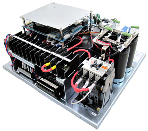
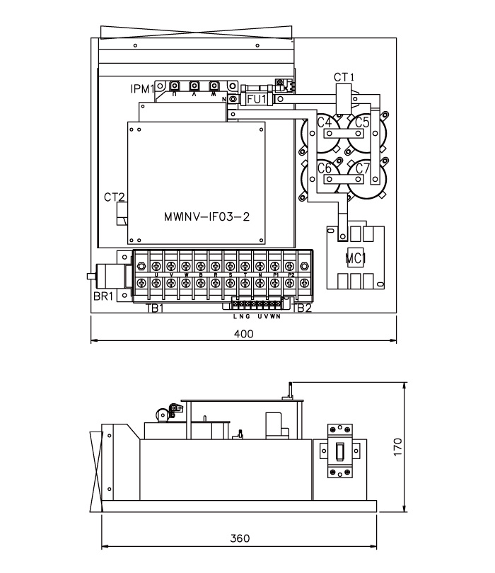
MWINV-9R144Inverter unit (9.1kVA)

| ■Rated Capacity | 9.1kVA(Output AC400V) |
| ■Rated Output Current | AC13.2Arms |
| ■Input Voltage | AC0 ~ 440Vrms DC0 ~ 700V |
| ■Control Power | AC85 〜 264Vrms |
| ■Breaker | Built In |
| ■Built In Sensor | Vdc, Idc, Iu, Iw, Vuv, Vwv |
| ■Protection Features | Overcurrent, Overvoltage, Temperature |
| Cooling Fan | Breaker | AC Input | DC Input |
| Built In | Built In | ○ | ○ |
| Parameters | Specifications | Reference | |
|---|---|---|---|
| AC Output | Rated Capacity | 9.1kVA(Output AC400V) 10.0kVA(Output AC440V) |
At switching frequency of 15kHz during forced air cooling |
| Rated Current | AC13.2Arms | ||
| Voltage Range | AC0 ~ 440Vrms | Depend on input voltage | |
| DC Input | Rated Voltage | DC700V | |
| Rated Current | DC14.5A | Calculated assuming 90% efficiency | |
| Voltage Range | DC0 ~ 700V | ||
| AC Input | Rated Voltage | AC400Vrms | |
| Rated Current | AC14.6Arms | Calculated assuming 90% efficiency | |
| Voltage Range | AC0 ~ 440Vrms | ||
| Cooling Method | Forced air cooling | ||
| Overload Capacity | 120%/min | ||
| Switching Frequency | ~ 20kHz | Derating necessary for 15kHz and above | |
| Dead Time | 4.0µsec or more | ||
| Sensor Monitor | DC Voltage(Vdc) | ±1000V / ±5V | |
| DC Current(Idc) | ±62.5A / ±5V | ||
| U phase / W phase Current (Iu / Iw) | ±31.25A / ±5V | ||
| UV / WV Inter Voltage (Vuv / Vwv) |
±1000V / ±5V | ||
| Control Power Voltage | AC85 〜 264Vrms | Supplies to the control board | |
| DC24V(22.8V~25.2V) | |||
| Insulation Resistance | 100MΩ or more | Main circuit-pair control circuit & FG in batch | |
| Control circuit-pair main circuit & FG in batch | |||
| Dielectric Strength Voltage | AC2500V / min | Main circuit-pair control circuit & FG in batch | |
| AC500V / min | Control circuit-pair main circuit & FG in batch | ||
| Dimensions | 400mm(W)×170mm(H)×360mm(D) | Projections excluded | |
| Weight | 12.5kg | ||

| Pin No | I / O | Description |
|---|---|---|
| 1 | O | Supplies -15V to the control board |
| 2,3 | ― | Ground |
| 4 | O | Supplies +15V to the control board |
| 5 | O | Outputs analog value of Vuv [±5V] |
| 6 | O | Outputs analog value of Vwv [±5V] |
| 7 | O | Outputs analog value of Iu [±5V] |
| 8 | O | Outputs analog value of Iw [±5V] |
| 9 | O | Outputs analog value of Vdc [+5V] |
| 10 | O | Outputs analog value of Idc [±5V] |
| 11 | O | Outputs analog value AN0 from SMB1 |
| 12 | O | Outputs analog value AN1 from SMB2 |
| 13 | ― | ― |
| 14 | I | H/W error reset signal |
| 15 | I | Drive signal of electromagnetic switch for inrush current prevention |
| 16 | I | Break drive signal |
| 17 | O | Reset signal(active LOW) |
| 18 | O | H/W error(active LOW) |
| 19 | I | U-phase P arm gate signal (active LOW) |
| 20 | I | U-phase N arm gate signal (active LOW) |
| 21 | I | V-phase P arm gate signal (active LOW) |
| 22 | I | V-phase N arm gate signal (active LOW) |
| 23 | I | W-phase P arm gate signal (active LOW) |
| 24 | I | W-phase N arm gate signal (active LOW) |
| 25〜30 | ― | ― |
| 31,32 | O | Supplies +5V to the control board |
| 33,34 | ― | Ground |