Development Tools
Product Information
Videos

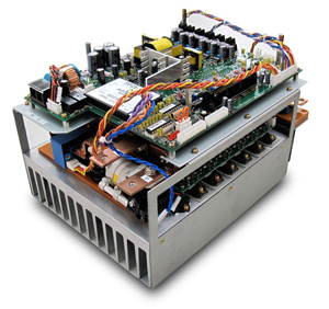
PE-Inverter series
MWINV-7R006AInverter unit (7kVA)

| ■Rated Capacity |
7.0kW |
| ■Rated Output Current |
AC100Arms |
| ■Input Voltage |
DC10 〜 80V |
| ■Control Power |
DC12V |
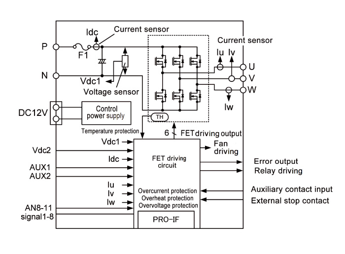
| ■Built In Sensor |
Vdc, Idc, Iu, Iw, Iv |
| ■Protection Features |
Overcurrent, Overvoltage, Temperature |
| Cooling Fan |
Breaker |
AC Input |
DC Input |
| Built In |
× |
× |
◯ |
| Parameters |
Specifications |
Reference |
| AC Output |
Rated Capacity |
7.0kVA |
|
| Rated Current |
100A |
|
| Output Frequency |
DC~440Hz |
|
| DC Input |
Rated Voltage |
60V |
|
| Voltage Range |
10~80V |
|
| Cooling Method |
Forced Air Cooling |
Fan operation by the temperature detecting |
| Overload Capacity |
120A / 1min |
Input DC60V |
| 200Apeak / 1sec |
Input DC60V |
| Switching Frequency |
10~40kHz |
|
| Sensor Monitor |
DC Voltage1(Vdc) |
±100V /±5V |
|
| U-phase / W-phase current (iu / iw) |
±300A /±5V |
|
| DC Current (idc) |
±300A /±5V |
|
| UV / WV inter voltage (Vuv / Vwv) |
±100V /±5V |
|
| Control Power Voltage |
DC12V(9.6~14.4V) |
|
| Dielectric Resistance |
100MΩ and above |
Main circuit-pair control circuit & FG in batch |
| Dielectric Voltage |
AC1500V / 1min |
Main circuit-pair control circuit & FG in batch |
| AC500V / 1min |
Control circuit-pair main circuit & FG in batch |
| Weight |
7.5kg |
|

| Pin No |
I / O |
Description |
| 1〜8 |
― |
External input/output signal (Connector relay only) |
| 9,10 |
― |
Digital GND |
| 11 |
― |
Analog input(Connector relay only) |
| 12 |
― |
Analog input(Connector relay only) |
| 13 |
― |
Analog input(Connector relay only) |
| 14 |
― |
Analog input(Connector relay only) |
| 15,16 |
― |
Analog GND |
| 17 |
O |
-15V analog power supply |
| 18,19 |
O |
Analog GND |
| 20 |
O |
+15V analog power supply |
| 21 |
O |
Analog output CH0 (AUX1) [±5V] |
| 22 |
O |
Analog output CH4 (AUX2) [±5V] |
| 23 |
O |
Analog output CH1 (Iu) [±5V] |
| 24 |
O |
Analog output CH5 (Iw) [±5V] |
| 25 |
O |
Analog output CH2 (Vdc1) [±5V] |
| 26 |
O |
Analog output CH6 (Idc) [±5V] |
| 27 |
O |
Analog output CH3 (Iv) [±5V] |
| 28 |
O |
Analog output CH7 (Vdc2) [±5V] |
| 29 |
― |
― |
| 30 |
I |
Reset signal input/DO16 |
| 31 |
I |
RLY1 driving signal input/DO8 |
| 32 |
I |
FAN driving signal input/DO9 |
| 33 |
O |
External auxiliary input signal DI14 |
| 34 |
O |
External error input signal/DI15 |
| 35 |
I |
PWM signal output UP0 |
| 36 |
I |
PWM signal output UN0 |
| 37 |
I |
PWM signal output VP0 |
| 38 |
I |
PWM signal output VN0 |
| 39 |
I |
PWM signal output WP0 |
| 40 |
I |
PWM signal output WN0 |
| 41〜46 |
― |
― |
| 47,48 |
O |
Digital power supply |
| 49,50 |
O |
Digital GND |