Development Tools
Product Information
Videos

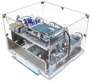
PE-Inverter series
MWINV-2044-SICSiC device modular inverter (20.7kVA)

| ■Rated Capacity |
20.7kVA |
| ■Rated Output Current |
AC30Arms |
| ■Input Voltage |
DC0 ~ 800V |
| ■Control Power |
AC90 〜 240Vrms |
| ■Built In Sensor |
Vdc, Vu, Vw, Idc, Iu, Iw, TH |
| ■Protection Features |
Overcurrent, Overvoltage, Overtemperature |
| ■External Dimensions |
W438×D450×H309.5(mm) |
| Cooling Fan |
Breaker |
AC Input |
DC Input |
| Built In |
× |
× |
○ |
| Items |
Specifications |
Reference |
| AC Output |
Rated capacity |
20.7kVA |
|
| Rated voltage |
AC400Vrms |
|
| Rated current |
AC30Arms |
Max AC40Arms (@DC400V) |
| DC Input |
Rated voltage |
DC700V |
|
| Rated current |
DC31A |
Calculated assuming 95% efficiency |
| Maximum current |
DC39A |
AC400Vrms, AC35Arms, DC650V, assuming 95% efficiency |
| Input voltage range |
DC0 ~ 800V |
|
| Cooling Method |
Forced Air Cooling |
|
| Switching Frequency |
〜200kHz |
Derating necessary above 50kHz. Rated frequency is 50kHz |
| Dead Time |
500nsec or more |
|
| Sensor Monitor |
DC Voltage(Vdc) |
+1000V /±5V |
|
| DC Current(idc) |
±50A /±5V |
|
| U phase / W phase current (Iu/Iw) |
±50A /±5V |
|
| U phase voltage (Vu) |
±1000V /±5V |
|
| W phase voltage (Vw) |
±1000V /±5V |
|
| Control Power Voltage |
AC90〜240Vrms |
|
| Insulation Resistance |
100MΩ or more |
Main circuit-pair control circuit & FG in batch |
| Control circuit-pair main circuit & FG in batch |
| Dielectric Strength Voltage |
AC2500V/minute |
Main circuit-pair control circuit & FG in batch |
| AC500V/minute |
Control circuit-pair main circuit & FG in batch |
| Weight |
18kg |
|


| Pin No |
I / O |
Description |
| 1〜14 |
― |
― |
| 15,16 |
― |
Ground |
| 17 |
O |
Supplies -15V to the control board |
| 18,19 |
― |
Ground |
| 20 |
O |
Supplies +15V to the control board |
| 21 |
O |
Outputs analog value of Vuv [±5V] |
| 22 |
O |
Outputs analog value of Vwv [±5V] |
| 23 |
O |
Outputs analog value of Iu [±5V] |
| 24 |
O |
Outputs analog value of Iw [±5V] |
| 25 |
O |
Outputs analog value of Vdc [±5V] |
| 26 |
O |
Outputs analog value of Idc [±5V] |
| 27 |
O |
Outputs temperature of heatsink at U-phase [±5V] |
| 28,29 |
― |
― |
| 30 |
I |
H/W error reset input signal (active LOW) |
| 31 |
I |
Relay drive input signal (active LOW) |
| 32 |
― |
― |
| 33 |
O |
Reset output signal (active LOW) |
| 34 |
O |
H/W error output signal (active LOW) |
| 35 |
I |
U-phase P arm gate signal (active LOW) |
| 36 |
I |
U-phase N arm gate signal (active LOW) |
| 37 |
I |
V-phase P arm gate signal (active LOW) |
| 38 |
I |
V-phase N arm gate signal (active LOW) |
| 39 |
I |
W-phase P arm gate signal (active LOW) |
| 40 |
I |
W-phase N arm gate signal (active LOW) |
| 41〜46 |
― |
― |
| 47,48 |
O |
Supplies +5V to the control board |
| 49,50 |
― |
Ground |