


Home > Power Electronics Development Tools > Inverter Unit PE-Inverter > MWINV-34044
Development Tools
Product Information
Videos

PE-Inverter series
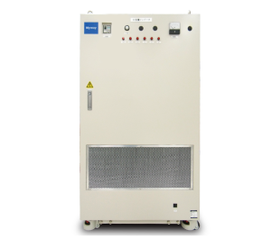
MWINV-34044Inverter unit (343kVA)

| ■Rated Capacity | 343kVA |
| ■Rated Output Current | AC450Arms |
| ■Input Voltage | DC0 ~ 850V |
| ■Control Power | AC180 〜 230Vrms |
| ■Built In Sensor | Vdc, Idc, Iu, lv, Iw |
| ■Protection Features | Overcurrent, Overvoltage, Temperature, Arm shortcircuit |
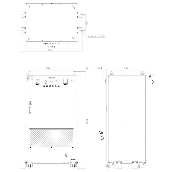
| ■External Dimensions | W880×D680×H1600(mm) |
| Cooling Fan | Breaker | AC Input | DC Input |
| Built In | × | × | ○ |
| Items | Specifications | Reference | |
|---|---|---|---|
| AC Output | Rated capacity | 200kW/343kVA | |
| Rated current | AC450Arms | ||
| Voltage Range | AC0~440Vrms | Switching frequency = 6kHz Dependent on input voltage and PWM modulation |
|
| DC Input | Rated Voltage | DC750V | |
| Voltage Range | DC0~850V | ||
| Cooling method | Forced air cooling | ||
| Overload capacity | 600Arms(10sec) 490Arms(120sec) |
Switching frequency = 6kHz Vdc:750V |
|
| Switching frequency | 1k~20kHz | Derating necessary for 6kHz and above | |
| Dead time | 3.5μsec or more | ||
| Sensors | DC voltage (Vdc) | 1040V / 5V | |
| DC current (Idc) | ±1000A / ±5V | ||
| U / V / W phase current (Iu/Iv/Iw) | ±1000A / ±5V | ||
| Control power supply voltage | AC180Vrms~230Vrms | ||
| Dielectric resistance | 100MΩ or more | ||
| Dielectric strength voltage | AC2500V / minute | Main circuit vs FG Main circuit vs control circuit Main circuit vs commercial power supply |
|
| AC1500V / minute | Commercial power supply vs control circuit commercial power supply vs FG |
||
| AC500V / minute | Control circuit vs FG | ||
| Weight | 350kg | ||

[Interface Board]
| Pin No. | I / O | Description |
|---|---|---|
| 1 | O | Supplies -15V to the control board |
| 2,3 | ― | Ground |
| 4 | O | Supplies +15V to the control board |
| 5 | O | Outputs analog value of Vuv |
| 6 | O | Outputs analog value of Vwv |
| 7 | O | Outputs analog value of Iu |
| 8 | O | Outputs analog value of Iw |
| 9 | O | Outputs analog value of Vdc |
| 10 | O | Outputs analog value of Idc |
| 11 | O | Outputs analog value of Iv |
| 12 | ― | ― |
| 13 | ― | ― |
| 14 | I | H/W error reset input signal (active LOW) |
| 15 | O | Gate power input signal |
| 16 | I | FAN drive input signal |
| 17 | ― | ― |
| 18 | O | H/W error output signal (active LOW) |
| 19 | I | U-phase P arm gate signal (active LOW) |
| 20 | I | U-phase N arm gate signal (active LOW) |
| 21 | I | V-phase P arm gate signal (active LOW) |
| 22 | I | V-phase N arm gate signal (active LOW) |
| 23 | I | W-phase P arm gate signal (active LOW) |
| 24 | I | W-phase N arm gate signal (active LOW) |
| 25〜30 | ― | ― |
| 31,32 | O | Supplies +5V to the control board |
| 33,34 | ― | Ground |
[Terminal Block]
| Pin No. | I / O | Description |
|---|---|---|
| 1〜8 | ― | ― |
| 9 | I | Output MC Drive Signal (active LOW) |
| 10 | I | Ground_24V |
| 11 | O | +24V |
| 12 | O | Output MC Response Signal (active LOW) |
| 13〜19 | ― | ― |
| 20 | ― | Earth terminal |